Department of the Army Technical Manual TM 10-751
Organist's Manual for Electronic Organ
AN/TNP-1
AN/TNP-1
(ZO WERD MODEL G IN HET LEGER GENOEMD!)
DEPARTMENT OF THE ARMY
Washington 25, D.C. 19 December 1949

Technical Manual 10-751 is published for the information and guidance of all concerned.
[AG 300.7 (25 Jul 49)]
By order of the Secretary of the Army:
Official:
J. LAWTON COLLINS
Chief of Staff, United States Army
EDWARD F. WITSELL
Major General
The Adjutant General
DESCRIPTION
Organist's Manual for Electronic Organ AN/TNP-1
Department of the Army Technical Manual TM 10-751
1. Purpose
Department of the Army • December 1949
The purpose of this manual is to provide sufficient fundamental information to enable experienced pianists and pipe organists to adapt their knowledge and technique to the operation of the electronic organ, AN/TNP-1. The instructions in this manual are not intended to teach organ technique or to guide inexperienced personnel. They are based upon the assumption that personnel who are planning to use the electronic organ have a fundamental musical understanding, a general knowledge of simple musical terms, such as those defined in appendix I, and ability to perform skillfully on piano, pipe organ, or other similar keyboard instrument.
This manual contains descriptions of major components of the electronic organ and information on its operation. It includes certain maintenance responsibilities of operating personnel, but does not include repair or maintenance procedures beyond the scope of the using organization.
The complete electronic organ, AN/TNP-1, is a self-contained, electro mechanical, sound-producing unit designed for operation on 120-volt, 60-cycle alternating current, or 120-volt, 50-cycle alternating current, as indicated on name plate, (see fig. 1). It makes use of the physical characteristics of sound to build musical tones from fundamental sounds that are electrically produced. The complete organ, consisting of a console, a tone cabinet and auxiliary equipment, is a movable unit which fits into a space approximately 4 feet square.
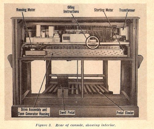
The console is a wooden cabinet similar in size and shape to the conventional pipe organ console. It contains the equipment required to select, generate, control, and partly amplify musical tones.
Hand Controls. The console has a slanting cover at the front that folds back upon the console top to reveal all hand controls used by the organist to produce music. Hand controls consist of manuals, drawbars, various switches and other control devices (see fig. 2)
United States Government Printing Office Washington: 1949
For sale by the Superintendent of Documents, U.S. Government Printing Office
Washington 25, D.C. - Price 15 cents
a.
Manuals.
Two manuals (keyboards played with the hands) are on the front of the console at playing level. They are in two horizontal tiers, the upper lying to the rear of the lower in stairstep fashion. The two manuals are identical, each consisting of 73 keys in two sizes. The color scheme of the 61 keys at the right of each manual, called playing keys, is exactly reverse to that of the remaining 12 at the left, called preset keys.
(a) Playing keys. b. (1) Pedal clavier. The pedal clavier is an assembly of 25 wooden pedals housed in a wooden framework. It sits at floor level in front of the wooden console cabinet. Pedals are provided in two designs and are colored in conventional organ fashion with 10 pedals having short black elevated foot contacts indented in the usual pattern between 15 flat-topped, light-colored pedals. Each pedal has a flexible metal strip fastened to its console end. When the organ is assembled, these pedal end strips slip into the base of the console cabinet. When pedals are pressed down, the end strips activate the electronic equipment required to transmit the pedal tones. (2) Swell pedal. The swell pedal is located near the center of the base shelf of the console. It consists of a rubber-padded footpiece connected with the interior of the organ by means of a crankshaft and rod assembly. When the toe of the footpiece is pushed, the organ volume is increased; when the heel is pushed, the volume is decreased. c. (1) Mechanical. The mechanical components of the console, consisting of a drive assembly between two motors, are on the console cabinet shelf. The drive assembly, concealed by a housing, consists of a drive shaft and numerous gears. It is started by a shaded pole starting motor located to its right. When the drive assembly is at operating speed, the shaded pole motor is stopped and released by a clutch from the assembly drive shaft to allow a synchronous-type running motor to keep the assembly operating at constant speed. The synchronous-type motor is coupled to the left of the drive assembly. (2) Electronic. The electronic components consist of tone generating units concealed with the drive assembly in the tone generator housing, a tremolant switch to produce a tremolo effect in the organ tone, a transformer and various other equipment for amplifying or producing organ tones. 20. Maintenance Responsibility Organizational maintenance, or routine preventive care and adjustment of the electronic organ will be performed by the organist or the using organization. Other maintenance should be referred through proper channels. a. (1) Field maintenance for class I and II installations, except at quartermaster class II installations having repair facilities, will be the responsibility of commanding generals of armies; of the Military District of Washington for areas under its control; and of major air force commanders for air force installations under their control. Field maintenance at specific installations may be otherwise assigned by mutual agreement or by direction of the Secretary of Defense in the interest of economy and efficiency. (2) Depot maintenance will be accomplished by the Quartermaster General in designated depot maintenance shops or through contractual services for the Departments of the Army and the Air Force.

b.
21. General Operative Care
It is the responsibility of every organist to keep the instrument he uses in the best possible condition. This entails frequent inspection, followed when necessary by reports of defective or unserviceable items. Reports should be made through channels, as indicated in paragraph 20. Equipment also must be protected against avoidable damage by keeping it clean and well lubricated.
22. Cleaning
a.
b.
c.
(1) Remove the organ bench.
(2) Lift the front of the pedal clavier and pull it slightly up and outward.
(3) Clean the pedal clavier with cheesecloth and dry-cleaning solvent. Sweep dust and lint from the floor.
(4) Replace pedal clavier by lifting slightly at the front and sliding the pedal contacts carefully into the base of the console.
(5) Replace the organ bench.
23. Lubricating
a.
|
Lubricant symbol |
Standard nomenclature |
|
RL* |
Oil, recoil, light. |
|
PL |
Oil, lubricating preservative, special. |
*Lubricant RL will ignite at 175° F. For this reason observe proper precautions to avoid overheating when handling or storing.
b.
(1) Remove rear organ panel by unscrewing the three thumbscrew bolts.
(2) Use lubricant PL to fill oil cups one-half full
(3) Replace rear organ panel.
5. Tone Cabinet
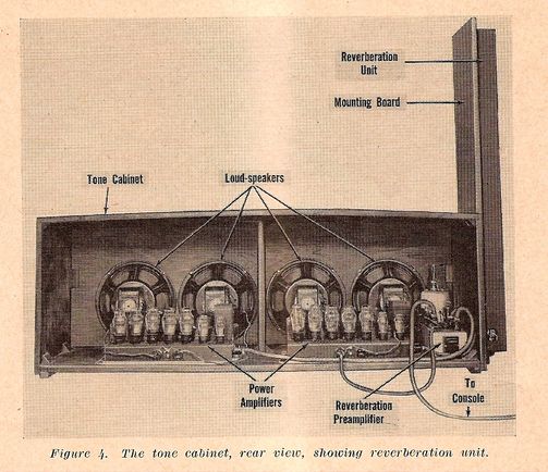
The tone cabinet consists of a wooden housing containing the electrical equipment and loud-speakers required to amplify the musical tones produced in the console (see fig. 4). The cabinet housing is a long, box-shaped structure open at the rear. Its front is a grille through which the organ is heard. The cabinet housing is divided into front and rear compartments by a partition extending lengthwise, parallel to and near the grille. Holes in this partition support, the mouths of four loud-speakers. Loud-speakers are electrically connected to two seven-tube power amplifiers and a reverberation preamplifier located in the rear compartment of the cabinet. An attachment called a reverberation unit is bolted to an upright mounting board on one side of the tone cabinet housing. The purpose of this unit is to lend an echo effect to the artificially formed organ tones, which might otherwise sound disagreeably abrupt.
c.
(1) Use screw driver to remove right-hand screws from the reverberation attachment protective cover. Swing the cover outward on its hinges.
(2) Use lubricant RL to fill the three long brass oil tubes to a point 1 inch from the top.
(3) Use lubricant RL to flIt the short oil tube as follows:
(a) To a point 2 inches from the top for operation in temperatures above 95° F.
(b) To a point 3 inches from the top for operation in temperatures between 50° and 95° F.
(c) To a point 4 inches from the top for operation in temperatures below 50
REVERBERATION ATTACHMENT. The reverberation attachment (see par. 5) consists of a spring assembly with springs enclosed within oil tubes (see fig. 6). Oil tubes must be inspected periodically and, when necessary, lubricated as follows:
4. Console
3. General
2. Scope